Showing posts with label Fe. Show all posts

Thursday, November 14, 2013

Production of High-Carbon Ferromanganese in Blast Furnace


Ferromanganese can be produced in Blast Furnace in a manner similiar to pig iron, however, in Western World only four producers employ this method. These are Thyasen Stahl (Germany), BSC Claveland (UK), SFPO (France), and Mizushima (Japan). The product produced from Blast Furnaces generally contains 76% Mn and 16% Fe.

Raw Material Selection and Pre-Treatment
The Raw materials required for the production of high-carbon ferromanganese are manganese ores, fluxes such as limestone, dolomite, or silica, and solid fuels and reductants such as coke.

In order to produce ferromanganese of the required grade a single ore seldom suitable because the desired Mn/Fe ratio of the charge determines the  Mn content of the final product. Ore from various source are therefore blended to achieve the ideal ratio and to limit the contents of the deleterious components silica, alumina, and phosphorus in the raw material mix.

The Raw material is crushed and screened to ca. 5-30 mm. Alternatively, sintered or pelletized fined ore can be used. Some deleterious components can be partially removed from the ore prior to melting by dense-medium separation or flotation. Slaging components (dolomite or limestone) can be added to the sintered or pelletized ore, which result in cost savings in the blast furnace. Partial reduction of the higher manganese oxides may also occur during sintering.

Blast Furnace Operation
In comparison to iron making, high gas temperatures are required in ferromanganese production because the reduction of manganese (II) oxide takes place at a higher temperature than is required for the reduction of wustite. This is achieved by oxygen enrichment of the hot blast or, in the case of SFPO, by heating the blast with non transferred arc plasma torches. The plasma arc increases the flame temperature from 2200 to 2800 oC and considerably reduces the coke consumption, which usually ranges from 1270 to 2000 Kg/t.

The recovey of manganese in the alloy is usually 75-85%. This is influenced by the MnO content of the slag, the slag to metal ratio, and losses in the flue gases. The MnO content of the slag is highly dependent on the basicity ration (CaO+MgO)/SiO2 (Figure 1), which can be controlled by the choice of the ore and addition of the flux. Losses to the flue gas can generally be recovered in the gas cleaning section.These materials can then be agglomerated and returned to the furnace.


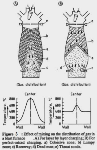
At the Mizushima work, the double bell valve of the conventional blast furnace have been replaced with an arrangement incorporating a distribution chute (figure 2). This results in a better distribution of the burden in the shaft and therefore a more even flow of gas though the burden (figure 3). The incorporation of distribution chute lowers the coke consumption of the furnace. 


In spite of innovations mentioned above the raw material costs of blast furnaces remain higher than those of submerged arc furnace due to high cost of coke. With the exception of SFPO, blast furnace production cost are higher than the average production cost of ferromanganese in electric furnaces.


The Reduction Process in The Blast Furnace
The reduction of the higher manganese oxides to manganese (II) oxide takes place in the upper zone of the shaft according to the reactions:
MnO2 + C = MnO + CO
MnO2 + CO = MnO + CO2
These generally occur below 900 oC and are indirect. The reactions are exothermic and the heat generated causes high top temperatures and necessitates water cooling of the furnace top.

The reduction of manganese (II) oxide MnO + C = Mn + CO is highly endothermic, in contrast to weakly endothermic reduction of wustite. This requires higher temperatures and, consequently, higher coke rates are required for the smelting of ferromanganese in blast furnaces.

Wednesday, October 23, 2013

The Iron-Carbon (Fe-C) and Iron-Cementite (Fe-Fe3C) Systems


Because carbon is a ubiquitous element in both iron- and steelmaking processes due to its essential use as a reductant during the extractive process of iron from its ores, carbon has   a predominant role in  siderurgy  (i.e., the metallurgy of iron and its alloys). Although other  alloying elements may be added to produce steels for special purposes, usually the structure of iron and steels is determined first by the content of carbon, secondly by the type of other alloying elements, and finally by the rate of cooling from the molten state. For all the above reasons, a solid grasp of the iron-carbon system is a mandatory step for understanding iron and iron alloys (i.e., steels and cast irons). As for the phase diagram of pure iron, the major phases occuring in the Fe-C phase diagram (Figure 1) can be accurately characterized by means of X-ray diffraction, thermal analysis, and dilatometry techniques. In practice, the iron-carbon phase diagram is a graphical plot of phases existing in thermodynamic equilibrium as a function of temperature versus the mass fraction of total carbon in the iron. The diagram depicted in this book is only a detail of the entire diagram. Actually, the phase diagram extends on the abscissa axis at left from pure iron free of carbon to a content of total carbon reaching 6.70 wt.% C that corresponds to the theoretical composition of iron carbide or cementite (Fe3C), while temperatures range from 200°C to 1600°C, the temperature at  which the system is fully liquid. The binary phase diagram exhibits, in addition to the four  critical points of the allotropes of pure iron, three other important characteristics:


(i) a eutectic point at 4.30 wt.% C and 1148°C;


(ii) a eutectoid point at 0.77 wt.% C and 727°C;

(iii) a peritectic transformation occurring at 1495°C.


Moreover, experimentally the following solid phases were identified.
 
Alpha-ferrite (α-ferrite, bcc). Sensu stricto and historically, ferrite consists of a solid solution of carbon inside a body-centered cubic crystal lattice in alpha-iron. The solubility of carbon in alpha-iron is extremely low, ca. 0.01 wt.% C at ambient temperature, and reaches only 0.025 wt.% C at 723oC. Therefore, at room temperature under conditions of equilibrium, any carbon present in excess of that small amount will exsolute in the form of cementite. Due to this low carbon content, some textbooks treat the ferrite phase substantially as pure iron, but this view must be discontinued to avoid confusion.  Usually, the ferrite of an alloyed steel may contain in solid solution appreciable amounts of other elements; ab extenso, any solid solution of which alpha-iron is the solvent is called ferrite (i.e., a solid solution of any element in alpha-iron). Alloying elements that stabilize ferrite are listed in Table 1.


Beta-ferrite (b-ferrite, bcc). Like alpha-ferrite, beta-ferrite consists of a solid solution of  any element in body-centered cubic beta iron.

Delta-ferrite (δ-ferrite, bcc).
Like alpha-ferrite, delta-ferrite consists of a solid solution of  any element in body-centered cubic delta iron. In the case of carbon, its maximum solubility in delta-iron is only 0.1 wt.% at 1487°C.
Gamma-austenite (g-austenite, fcc). Austenite is a solid insertion solution of carbon into the crystal lattice of face-centered cubic gamma-iron. It has been definitively established that the carbon atoms in austenite occupy interstitial positions in the face-centered cubic space lattice causing the lattice parameter to increase progressively with the carbon content.
 
Cementite. Cementite is an iron carbide with the chemical formula Fe3 C. At room temperature,   cementite is a hard, brittle, and ferromagnetic material with a Curie temperature of   210°C. It is formed by chemical reaction between iron and excess carbon. Three distinct origins must, however, be distinguished:


(i) primary cementite resulting from the separation during solidification of liquid iron with carbon content ranging between 4.3 wt.% and 6.69 wt.% C;


(ii) secondary cementite formed after demixion of carbon as a result of a decrease in miscibility during the cooling of ferrite;


(iii) tertiary cementite resulting from demixion during the cooling of austenite. Actually, at
room temperature under conditions of equilibrium, any carbon present in excess of that small amount must exist in a form other than that of a solute in a solid solution.

Perlite. A biphasic eutectoidic constituent that consists of an interlamellar growth of ferrite and cementite. Perlite is formed during the transformation of austenite with a eutectoid composition (i.e., 0.77 wt.% C).
 
Ledeburite. A biphasic eutectic constituent resulting from the solidification of a molten metal having a eutectic composition. Hence it consists of an austenite containing 1.7 wt.% C in solid solution and cementite.
 
In the phase diagrams in Figures 2.1 and 2.2, the transition temperatures or critical points   previously identified for the four iron allotropes must now be replaced by two temperature  limits or points. Actually, due to hysteresis phenomena occurring upon heating and cooling, the equilibrium curves are greatly influenced by the rate of cooling and heating, and they form distinct plots. The various temperatures at which pauses occur in the rise or fall of  temperatures when iron or steel is heated from room temperature or cooled from the molten  state are called arrest points, denoted by uppercase letter A. Due to the previously mentioned hysteresis behavior during heating and cooling, the arrest points obtained on heating   are denoted Ac and those obtained on cooling are denoted Arwhile arrest points at equilibrium are denoted Ae. Historically, the subscripts c , r, and e were derived from the first letters  of the French words chauffage (heating), refroidissement (cooling), and équilibre (equilibrium),  respectively. These arrest points are described in detail in Table 2.


From the iron-carbon phase diagram several important characteristics regarding the classification   of iron and iron alloys can be seen. Iron alloys are classified according to their total content of carbon. Steel are particular iron alloys having a carbon content below 2.1 wt.% C.  Above this limit, we have cast irons up to a practical limit of 3.75 wt.% C. A steel containing  0.77 wt.% C is called a eutectoid steel.  Eutectoid steel consists of an intimate mixture of alpha- ferrite and cementite forming an intergrowth of thin plates or lamellae known as perlite.  Therefore, a steel having a carbon content below 0.77 wt.% C is called a hypotectoid steel. Its  structure consists of a small amount of pearlite with an excess of alpha-ferrite, which collectsat the grain boundaries. Hypotectoid steels are hence softer and more ductile than eutectoid steels. On the other hand, a steel with more than 0.77 wt.% C is called a hypertectoid steel. Its   structure consists of pearlite with an excess of cementite. Hypertectoid steels are harder,  more brittle, and les ductile than eutectoid steels. Above 2.11 wt.% C, molten iron solidifies   always below 1350°C and the resulting low liquidus temperature iron alloys are called cast irons due to their ease of melting. The eutectic point in the Fe-C diagram is located at  4.3 wt.% C. At this composition, when the alloy solidifies, it forms a mixture of austenite  with 1.7 wt.% C in solid solution and cementite; this eutectic structure is called ledeburite. In  practice, cast irons exhibit a carbon content ranging between 2.11 and 3.75 wt.%. Upon cooling, cast irons exhibit a mixture of pearlite and cementite.


The iron-carbon phase diagram only applies to alloys that contain only iron and carbon. But because other desired or undesired alloying elements are usually originally present from the ironmaking process (e.g., O, C, Si, P, Mn, V) or are added intentionally (e.g., Ni, Cr, Mo), during steelmaking the iron-carbon phase diagram cannot show accurately the conditions that apply to actual steels. Hence it has to be modified appropriately to take into account the effect of the elements. These additional elements impact both the arrest points and equilibrium lines, and they also determine the existence or not of certain phases. Alloying elements with their related impact on iron-carbon phases are listed in Table 3.


Friday, October 11, 2013

Sponge Iron Making


The process of sponge iron manufacturing involves removal of oxygen from iron ore. When that happens, the departing oxygen causes micro pores in the ore body, turning it porous. When the eventual product is observed under a microscope, it resembles a honeycomb structure, which looks spongy in texture. Hence the name sponge iron.
 
The Main Raw Material are Primary ore Secondary Iron Ore (Magnetite or Hematite),  Iron sand also can be used but it should be a Pellet first. Beside that Non Cooking Coal for reduction and sometimes dolomite or Lime is needed to fix the Sulfur and or bacisity.

Fig 1. Example for Specification of Iron Ore


Fig 2. Rotary Kiln Cross Section
 

Coal based Direct reduction process is classified based on the reducing agent namely solid. Most solid reduction process use non-coking coal as reducing agent due to abundantly available non-coking coal. The process proposed to be adopted is the rotary kiln proposes using Non-coking coal and iron ore. Iron are undergoes the following reduction reaction in all the processes.


Based on Fig 3. seen that the reaction start at Temperature around 700 oC with 60% of CO at 1 atm. But Normally, the process is done at temperature 900-1100 oC.


Fig 3. Iron and Boudouard reaction Diagram


After processed in rotary kiln, the product sponge iron come to the water cooled cooler where its temperature reaches to 80 to 100°C. The Product is conveyed to the product separation and storage building.


Fig 4. Example of Spong Iron Specification


The Example of the Complete Flowsheet can be seen as figure 5.
 
 
Fig. 5 Process Flowsheet


Monday, December 1, 2008

Proses Pengolahan Nikel Menjadi FeNi Dari Bijih Laterite


Secara umum, mineral bijih di alam ini dibagi dalam 2 (dua) jenis yaitu mineral sulfida dan mineral oksida. Begitu pula dengan bijih nikel, ada sulfida dan ada oksida. Masing-masing mempunyai karakteristik sendiri dan cara pengolahannya pun juga tidak sama. Dalam bahasan kali ini akan dibatasi pengolahan bijih nikel dari mineral oksida (Laterit).

Bijih nikel dari mineral oksida (Laterite) ada dua jenis yang umumnya ditemui yaitu Saprolit dan Limonit dengan berbagai variasi kadar. Perbedaan menonjol dari 2 jenis bijih ini adalah kandungan Fe (Besi) dan Mg (Magnesium), bijih saprolit mempunyai kandungan Fe rendah dan Mg tinggi sedangkan limonit sebaliknya. Bijih Saprolit dua dibagi dalam 2 jenis berdasarkan kadarnya yaitu HGSO (High Grade Saprolit Ore) dan LGSO (Low Grade Saprolit Ore), biasanya HGSO mempunyai kadar Ni ≥ 2% sedangkan LGSO mempunyai kadar Ni <>


Tabel 1. Contoh Komposisi Saprolit Ore

Berdasarkan table 1, faktor yang paling penting diperhatikan adalah basisitas (tingkat kebasaan) MgO/SiO2 atau ada juga yang mengukur berdasarkan SiO2/MgO. Tingkat kebasaan ini menentukan brick/ refractory/bata tahan api yang harus digunakan di dalam tungku (furnace), jika basisitas tinggi maka refractory yang digunakan juga sebaiknya mempunyai sifat basa agar slag (terak) tidak bereaksi dengan refractory yang akan menghabiskan lapisan refractory tersebut. Basisitas juga menentukan viscositas slag, semakin tinggi basisitas maka slag semakin encer dan mudah untuk dikeluarkan dari furnace. Namun basisitas yang terlalu tinggi juga tidak terlalu bagus karena difusi Oksigen akan semakin besar sehingga kehilangan Logam karena oksidasi terhadap logam juga semakin besar.


Gambar 1. Kesetimbangan Metal-Slag

(Ket: Slag selalu berada di atas metal karena densitynya lebih rendah)

Secara umum proses pengolahan bijih nikel jalur pyrometallurgy dibagi dalam beberapa tahap seperti dalam diagram berikut:

Gambar 2. Diagram alir proses
1. Kominusi
Kominusi adalah proses reduksi ukuran dari ore agar mineral berharga bisa terlepas dari bijihnya. Berbeda dengan pengolahan emas, dalam tahap kominusi untuk nikel ore ini hanya dibutuhkan ukuran maksimal 30 mm sehingga hanya dibutuhkan crusher saja dan tidak dibutuhkan grinder.
2. Drying
Drying atau pengeringan dibutuhkan untuk mengurangi kadar moisture dalam bijih. Biasanya kadar moisture dalam bijih sekitar 30-35 % dan diturunkan dalam proses ini dengan rotary dryer menjadi sekitar 23% (tergantung desain yang dibuat). Dalam rotary dryer ini, pengeringan dilakukan dengan cara mengalirkan gas panas yang dihasilkan dari pembakaran pulverized coal dan marine fuel dalam Hot Air Generator (HAG) secara Co-Current (searah) pada temperature sampai 200 C.

3. Calcining
Tujuan utama proses ini adalah menghilangkan air kristal yang ada dalam bijih,air kristal yang biasa dijumpai adalah serpentine (3MgO.2SiO2.2H2O) dan goethite (Fe2O3.H2O). Proses dekomposisi ini dilakukan dalam Rotary Kiln dengan tempetatur sampai 850 oC menggunakan pulverized coal secara Counter Current. Reaksi dekomposisi air kristal yang terjadi adalah sebagai berikut:

a. Serpentine

Reaksi dekomposisi dari serpentine adalah sebagai berikut:

3MgO.2SiO2.2H2O = 3 MgO + 2 SiO2 + 2 H2O

Reaksi ini terjadi pada temperatur 460-650 C dan tergolong reaksi endotermik. Pemanasan lebih lanjut MgO dan SiO2 akan membentuk forsterite dan enstatite yang merupakan reaksi eksotermik.

2 MgO + SiO2 = 2MgO.SiO2
MgO + SiO2 = MgO.SiO2

b. Goethite

Reaksi dekomposisi dari goethite adalah sebagai berikut:

Fe2O3.H2O = Fe2O3 + H2O

Reaksi ini terjadi pada 260C – 330C dan merupakan reaksi endotermik.

Di samping menghilangkan air kristal, pada proses ini juga biasanya didesain sudah terjadi reaksi reduksi dari NiO dan Fe2O3. Dalam teknologi Krupp rent, semua reduksi dilakukan dalam rotary kiln dan dihasilkan luppen. Sedangkan dalam technology Electric Furnace, hanya sekitar 20% NiO tereduksi secara tidak langsung dalam rotary kiln menjadi Ni dan 80% Fe2O3 menjadi FeO sedangkan sisanya dilakukan dalam electric furnace.

Produk dari rotary kiln ini disebut dengan calcined ore dengan kandungan moisture sekitar 2% dan siap dilebur dalam electric furnace.

4. Smelting
Proses peleburan dalam electric furnace adalah proses utama dalam rangkaian proses ini. Reaksi reduksi 80% terjadi secara langsung dan 20% secara tidak langsung pada temperature sampai 1650 C. Reaksi reduksi langsung yang terjadi adalah sebagai berikut:

NiO(l) + C(s) = Ni(l) + CO(g)
FeO(l) + C(s) = Fe(l) + CO(g)

Beberapa material yang mempunyai afinitas yang tinggi terhadap oksigen juga tereduksi dan menjadi pengotor dalam logam.

SiO2(l) + 2C(s) = Si(l) + 2CO(g)
Cr2O3(l) + 3C(s) = 2Cr(l) + 3CO(g)
P2O5(l) + 5C(s) = 2P(l) + 5CO(g)
3Fe(l) + C(s) = Fe3C(l)

Karbon disupplay dari Antracite (tergantung desain), dan reaksi terjadi pada zona leleh elektroda. CO(g) yang dihasilkan dari reaksi ini ditambah dengan CO(g) dari reaksi boudoard mereduksi NiO dan FeO serta Fe2O3 melalui mekanisme solid-gas reaction (reaksi tidak langsung):

NiO(s) + CO(g) = Ni(s) + CO2(g)
CoO(s) + CO(g) = Co(s) + CO2(g)
FeO(s) + CO(g) = Fe(s) + CO2(g)
Fe2O3(s) + CO(g) = 2FeO(s) + CO2(g)

Oksida stabil seperti SiO2, Cr2O3 dan P2O5 tidak tereduksi melalui reaksi tidak langsung. Sampai di sini Crude Fe-Ni sudah terbentuk dan proses sudah bisa dikatakan selesai.

Yield (recovery) dari nikel pada EAF dapat didekati seperti pada gambar berikut:


Gambar 3. Hubungan antara Fe yield dan Ni yield dalam EAF
Gambar 4. Hubungan antara Fe yield dan %Ni dalam Crude FeNi


Gambar 5. Diagram fasa biner Fe-Ni


Pada daerah interface (antar muka) Slag-Metal terjadi kesetimbangan sebagai berikut:
Si(l) + 2FeO(l) = 2Fe(l) + SiO2(l)
Si(l) + 2NiO(l) = 2Ni(l) + SiO2(l)
NiO(slag) + Fe(metal) = Ni(metal) + FeO(slag)

Sekali lagi basisitas sangat penting dalam kondisi ini, sebagai contoh proses yang didesain dengan basisitas 0,68 maka:

MgO = 0.68SiO2

MgO + SiO2 = 100%
0.68SiO2 + SiO2 = 100%
1.68SiO2 = 100% ®
SiO2 = 59.5% dan MgO = 40.5%

Korelasi antara slag melting point pada SiO2 59.5% dan MgO 40.5% diilustrasikan oleh diagram terner FeO-MgO-SiO2 dalam gambar 6 (diambil dari Slag Atlas, Verlagstahleisen, M.B.H., Duesseldorf, 1981 and I.J. Reinecke and H. Lagendikj, INFACON XI Conference Proceeding, 2007).


Gambar 6. Diagram terner FeO-MgO-SiO2 yang menunjukkan hubungan antara slag melting point dan slag basicity of 0.68 & 0.5 untuk FeO 6% & 10%

5. Refining
Pada proses ini yang paling utama adalah menghilangkan/memperkecil kandungan sulfur dalam crude Fe-Ni dan sering disebut Desulfurisasi. Dilakukannya proses ini berkaitan dengan kebutuhan proses lanjutan yaitu digunakannya Fe-Ni sebagai umpan untuk pembuatan Baja dimana baja yang bagus harus mengandung Sulfur maksimal 20 ppm sedangkan kandungan Sulfur pada Crude Fe-Ni masih sekitar 0,3% sehingga jika kandungan sulfur tidak diturunkan maka pada proses pembuatan baja membutuhkan kerja keras untuk menurunkan kandungan sulfur ini.

Proses ini dilakukan pada ladle furnace dengan agent sebagai berikut:

Tabel 2. Agent Untuk desulfurisasi


Sedangkan reaksi yang terjadi adalah sebagai berikut:

CaC2 (S) + S = CaS (S) + 2C (Sat)
Na2CO3 + S + Si = Na2S + (SiO2) + CO
Na2Co3 + SiO2 = Na2O . SiO2 + CO2

Reaksi ini merupakan reaksi eksotermik sehingga tidak membutuhkan pemanasan lagi pasca smelting.

Proses selanjutnya adalah converting, sebenarnya proses ini masih dalam bagian refining hanya untuk membedakan antara menurunkan sulfida dengan menurunkan pengotor lain seperti Si, P, Cr dan C sesuai dengan kebutuhan. Sedangkan prosesnya sama hanya saja reaksi lebih dominan oksidasi dari oksigen.


Si (l) + O2 (g) = SiO2 (l) ↔ SiO2 (l) + CaO (l) = CaO . SiO2 (l)
Cr (l) + 5O2 (g)= 2Cr2O3 (l)
4P (l)+ 5O2 (g)= 2P2O5 (l) ↔CaO (l)+P2O5 (l)= CaO. P­2O5 (l)
C(l) + ½ O2 (g)= CO (g)
C(l) + O2 (g)= CO2 (g)


Tabel 3. Contoh Komposisi Crude Fe-Ni yang dihasilkan